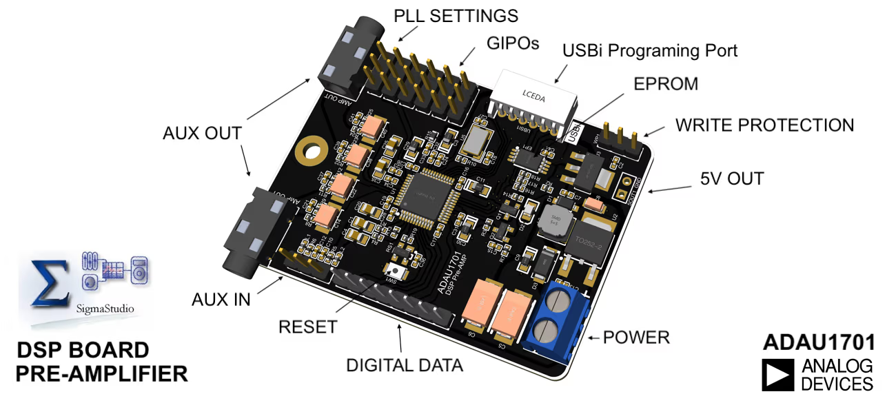
- 4 Channel Analog Output + 2 Digital Outputs
- Aux Input
- Digital Input
- 2 Analog Outputs
- 5VDC Power
- I2C Connection for USBi
- SigmaStudio Program loaded
- 4 Multipurpose Pin outs
- 28-/56-bit, 50 MIPS digital audio processor
- 2 ADCs: SNR of 100 dB, THD + N of −83 dB
- 4 DACs: SNR of 104 dB, THD + N of −90 dB
- Complete standalone operation
- Self-boot from serial EEPROM
- Auxiliary ADC with 4-input mux for analog control
- Fully programmable with SigmaStudio™ graphical tool
- GPIOs for digital controls and outputs
- 28-bit × 28-bit multiplier with 56-bit accumulator for full double-precision processing
- Clock oscillator for generating a master clock from crystal
- PLL for generating master clock from 64 × fS,256 × fS, 384 × fS, or 512 × fS, clocks
- ROHS Compliant
- AUX 1 Out : Left Treble, Left BASS
- AUX 2 OUT : Right Treble, Right BASS
- Digital Out 1 : Left Sub Woofer Out
- Digital Out 2 : Right Sub Woofer Out
- Download Default Program
- Download SignaStudio™ From Analog Device
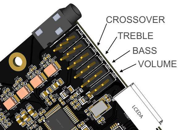
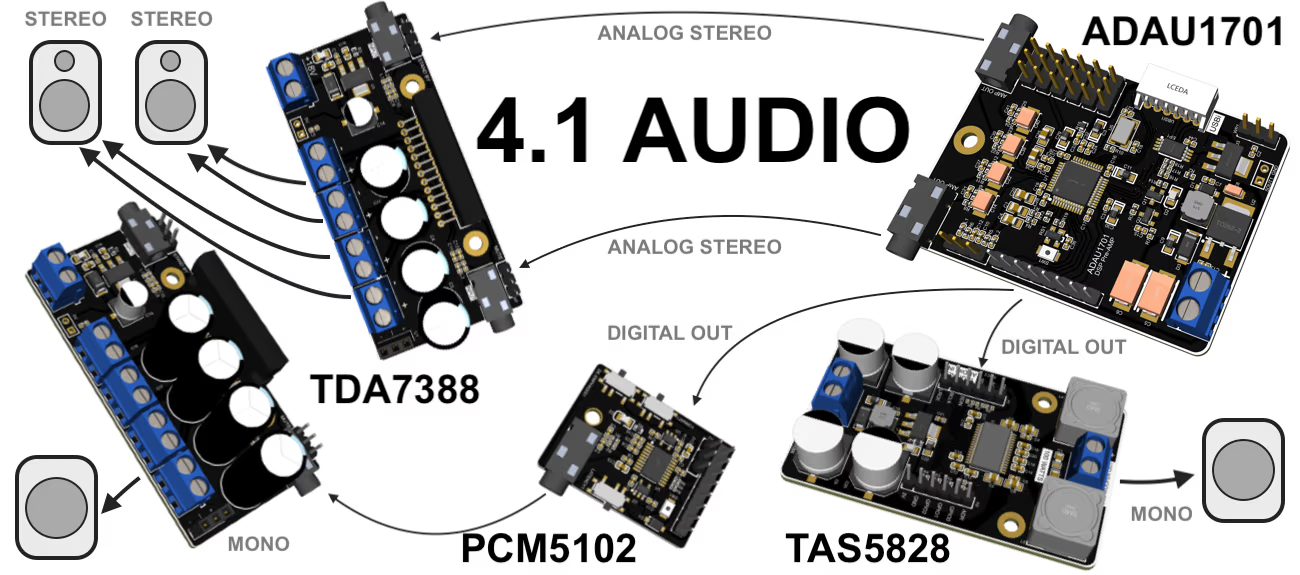
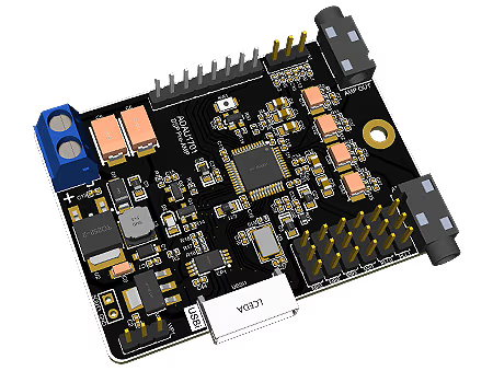
This small 70x45 mm device is capable of handling every requirement to process your analog as well as digital audio. You can build stereo, 2 channel, 2.1 channel, 4 channel or even 4.1+ audio systems by using this device. Device runs in both Master & Slave mode.
Device has 4 GPIOs which can be configured to connect potentiometers, LEDs or other components. It has flexibility, where you can connect Bluetooth devices with both Digital or Analog outputs.
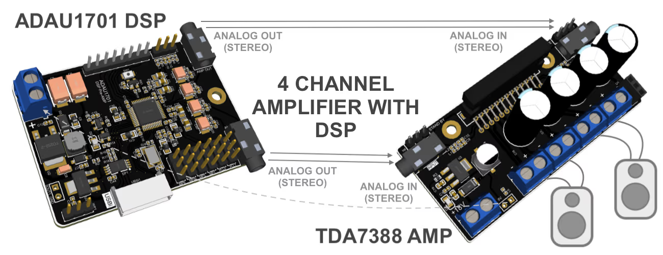
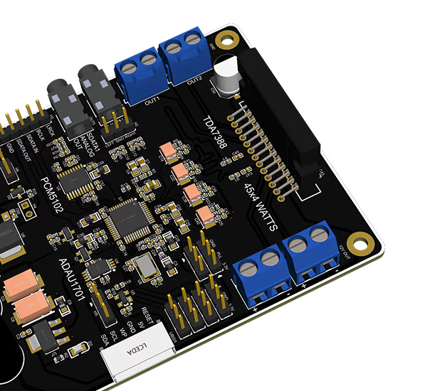
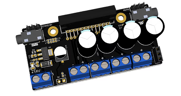
Build stereo, 2-channel, 2.1-channel or 4-channel audio systems with ADAU1701 + TDA7388 QUAD Amplifier on the fly. You can power TDA7388 with up to 18V DC and power ADAU1701 DSP with the 5V DC Out from TDA7388. Connect 3.5 mm Audio cables from DSP to amplifier, connect 4 speakers and your 4-channel audio system is ready.
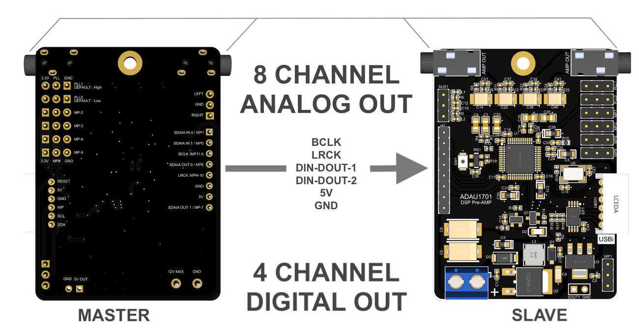
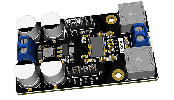
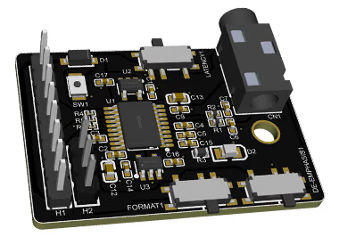
You can additionally connect 100W TAS5828m Mono Amplifier with the existing setup by simply connecting Digital Out from ADAU1701 DSP to Digital Input to TAS5828m. You must power TAS5828M separately.
Other Specifications
| Dimensions | 45mm x 60mm |
|---|---|
| Min Input Voltage | 5V |
| Max Input Voltage | 20V |
| Max Input Current | 1A |
| Mounting Screw Holes | 30mm x 1 |
| Analog Input | 2.54mm x 1 header |
| Analog Output | 4 Channels |
| Output Jacks | 3.5mm x 2 |
| Digital Outputs | 2.54mm headers x 2 |
| Digital Inuts | 2.54mm headers x 2 |
| I2C Programing Port | JST, PH, S6B, 6 Way, 1 Row,Right Angle PCB Head |
| PLL Setting | 2.54mm headers x 2 |
| USBi | Any CY7C68013A chipset based USBi (Not included) |
| Programing Software | SigmaStudio™ by Analog Device |
| EPROM Memory | 256kb |
| GPIOs | 2.54mm headers x 4 |
Header Connections
| AUX1: Analog Audio Input |
|
||||||||||||||||
|---|---|---|---|---|---|---|---|---|---|---|---|---|---|---|---|---|---|
| H1: Digital Input Output |
|
||||||||||||||||
| 5OUT1: 5V Out |
|
||||||||||||||||
| WP1: Write Protect |
Connect PIN 1 & 2 via Jumper to disable write protect on EPROM |
||||||||||||||||
| PLL0: PLL0 settings for ADAU1701 |
|
||||||||||||||||
| PLL1: PLL1 settings for ADAU1701 |
|
||||||||||||||||
| MP2: GPIO pin for ADAU1701 |
|
||||||||||||||||
| MP3: GPIO pin for ADAU1701 |
|
||||||||||||||||
| MP8: GPIO pin for ADAU1701 |
|
||||||||||||||||
| MP9: GPIO pin for ADAU1701 |
|
||||||||||||||||
| USBi: I2C Programing port for ADAU1701 |
|
Audio Output Jacks
| AMP POUT | 3.5mm Audio Jack for Analog Signal Out to Amplifier. |
|---|---|
| AMP POUT | 3.5mm Audio Jack for Analog Signal Out to Amplifier. |
Board Connectors
| U11: Power Input | Min: 5V, MAX: 20V DC. |
|---|

PRODUCTS
enovo-77
enovo-tda-7
enovo-tas-5
enovo-dsp-7
enovo-dac-5
enovo-32
enovo-32-mini
Visit Amazone Store