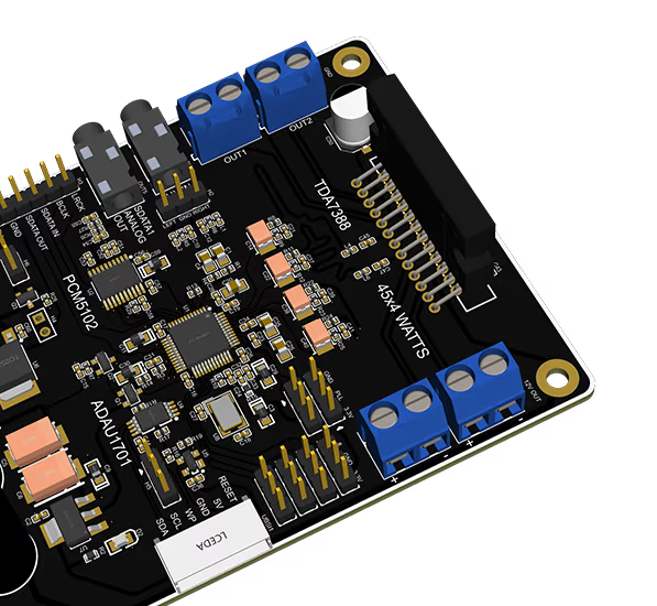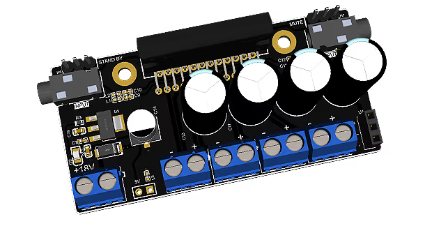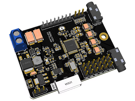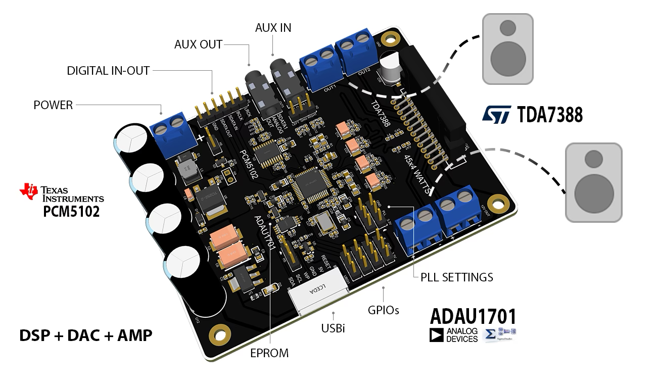

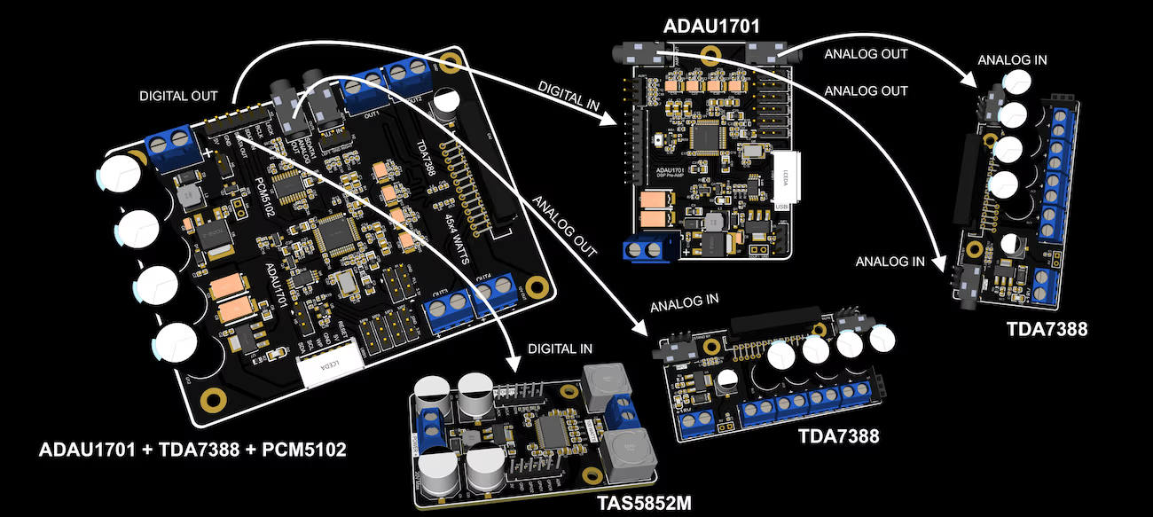
Enovo-77 is a class-AB quad bridge amplifier with DSP. You can control TDA7388 amplifier with ADU1701 on-board DSP via SigmaStudio software. With on-board DSP you can add various crossovers, equalizers, effects to the amplifier. Along with on-board DSP, Enovo-77 also has a on-board PCM5102 DAC (digital to analog converter) connected to DSP's SDATA_OUT, MCLK & BCLK, which outputs Analog signal via AUX connector. You can program which output as Sub-woofer out or even stereo out and connect either a subwoofer amplifier or another Enovo-77 together to output 4.1, 4,2, 6.1, 8.0, 8.1 or 8.2 channel outputs.
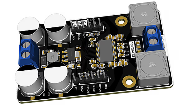
You can club together multiple systems to build 4.1 or more channel amplifiers. Connect DSP Board to the Digital Out from Master DSP on the amplifier which you can use to connect either TDA7388 4 channel amplifier along with TAS5828m Mono amplifier or directly connect Master DSP to TAS5828m.
| System | Options | Difficulty Level |
|---|---|---|
| Stereo | enovo-77 You can either use only 2 Outputs from enovo-77 to run a stereo system or combine 2 left & 2 right channels for more power. |
Plug-n-Play |
| 2.1 | enovo-77 You can 2 Outputs from enovo-77 to run left-right channel and combine 2 channels as Mono Sub-woofer. |
Medium |
| 4.0 | enovo-77 You can either use each output from enovo-77 to run left-right Tribal & left-right Bass. |
Plug-n-Play |
| 4.1 | enovo-77 + enovo-tas-5 You can either use each output from enovo-77 to run left-right Tribal & left-right Mid and use Digital Out from enovo-77 as Digital In for enovo-tas-5. |
Pro |
| 8.0 | enovo-77 + enovo-77 You can use Digital Out from one enovo-77 (set as master) as Digital In for enovo-77 (set as slave) to run 8.0 syetem. |
Pro |
| 8.2 | enovo-77 + enovo-77 + enovo-tas-5 You can use Digital Out from one enovo-77 (set as master) as Digital In for enovo-77 (set as slave) to run 8.0 system, additionally you can use Digital Audio from enovo-77 (set as slave) as Digital In for enovo-tas-5 |
Pro |
| Dimensions | 90mm x 70mm |
|---|---|
| Min Input Voltage | 12V |
| Max Input Voltage | 20V |
| Max Input Current | 1A |
| Mounting Screw Holes | 30mm x 4 |
| Analog Input | 2.54mm x 1 header + 3.5mm Audio Jack |
| Analog Output | 4 Channels Speaker Out + 2 Channel Analog Out via 3.5mm Audio jack |
| Output Jacks | 3.5mm x 1 |
| Digital Outputs | 2.54mm headers x 1 |
| Digital Inputs | 2.54mm headers x 1 |
| PLL Setting | 2.54mm headers x 2 |
| USBi | Any CY7C68013A chipset based USBi (Not included) |
| I2C Programing Port | JST, PH, S6B, 6 Way, 1 Row,Right Angle PCB Head |
| Programing Software | SigmaStudio™ by Analog Device |
| Functions | In-built Amplifier+DAC mute & stand by functions. |
| EPROM Memory | 256kb |
| GPIOs | 2.54mm headers x 4 |
| Amplifier Shutdown | 2.54mm headers x 1 |
| V-Out Shutdown | 2.54mm headers x 1 5V Out |
| Chipsets Onboard | ADAU1701 + PCM5102 + TDA7388 |
| Speaker Recommendations | 4 x 45 W / 4 Ω max. 4 x 26 W / 4 Ω @ 14.4 V, 1 kHz, 10 % |
| H2: Analog Audio Input |
|
||||||||||||
|---|---|---|---|---|---|---|---|---|---|---|---|---|---|
| H3: Digital Input Output |
|
||||||||||||
| H4: 5V Out |
|
||||||||||||
| H5: Write Protect |
Connect PIN 1 & 2 via Jumper to disable write protect on EPROM |
||||||||||||
| H5: 5V Out |
Connect PIN 1 & 2 via Jumper to enable (turn on) on-board amplifier. Remove the jumper to turn the amplifier off. You can also connect external stitch to this header. |
||||||||||||
| PLL0: PLL0 settings for ADAU1701 |
|
||||||||||||
| PLL1: PLL1 settings for ADAU1701 |
|
||||||||||||
| MP2: GPIO pin for ADAU1701 |
|
||||||||||||
| MP3: GPIO pin for ADAU1701 |
|
||||||||||||
| MP8: GPIO pin for ADAU1701 |
|
||||||||||||
| MP9: GPIO pin for ADAU1701 |
|
||||||||||||
| USBi: I2C Programing port for ADAU1701 |
|
| AUX1 (H1): Analog Audio Input | 3.5mm Audio Jack for AUX in from Bluetooth devices or other devices. |
|---|---|
| OUT5 : Analog Audio Output | 3.5mm Audio Jack for Analog Audio Out from on-board (PCM5102) DAC to sub-woofer amplifier. |
| IN1: Power Input | Min: 12V, MAX: 20V DC. |
|---|---|
| OUT1 : Analog Audio Output | Speaker out for DAC0 |
| OUT2 : Analog Audio Output | Speaker out for DAC1 |
| OUT3 : Analog Audio Output | Speaker out for DAC2 |
| OUT4 : Analog Audio Output | Speaker out for DAC3 |
